We offer a wide range of enthalpy exchangers suitable for most heat recovery units. If you can't find the right model, don't hesitate to contact us – we will be happy to help!


regulation for a system with EC fans,
frost protection or BY-PASS control
programming of ventilation intensity,
monitoring filter replacement,
quick ventilation - control from the toilet,
GENERAL INFORMATION
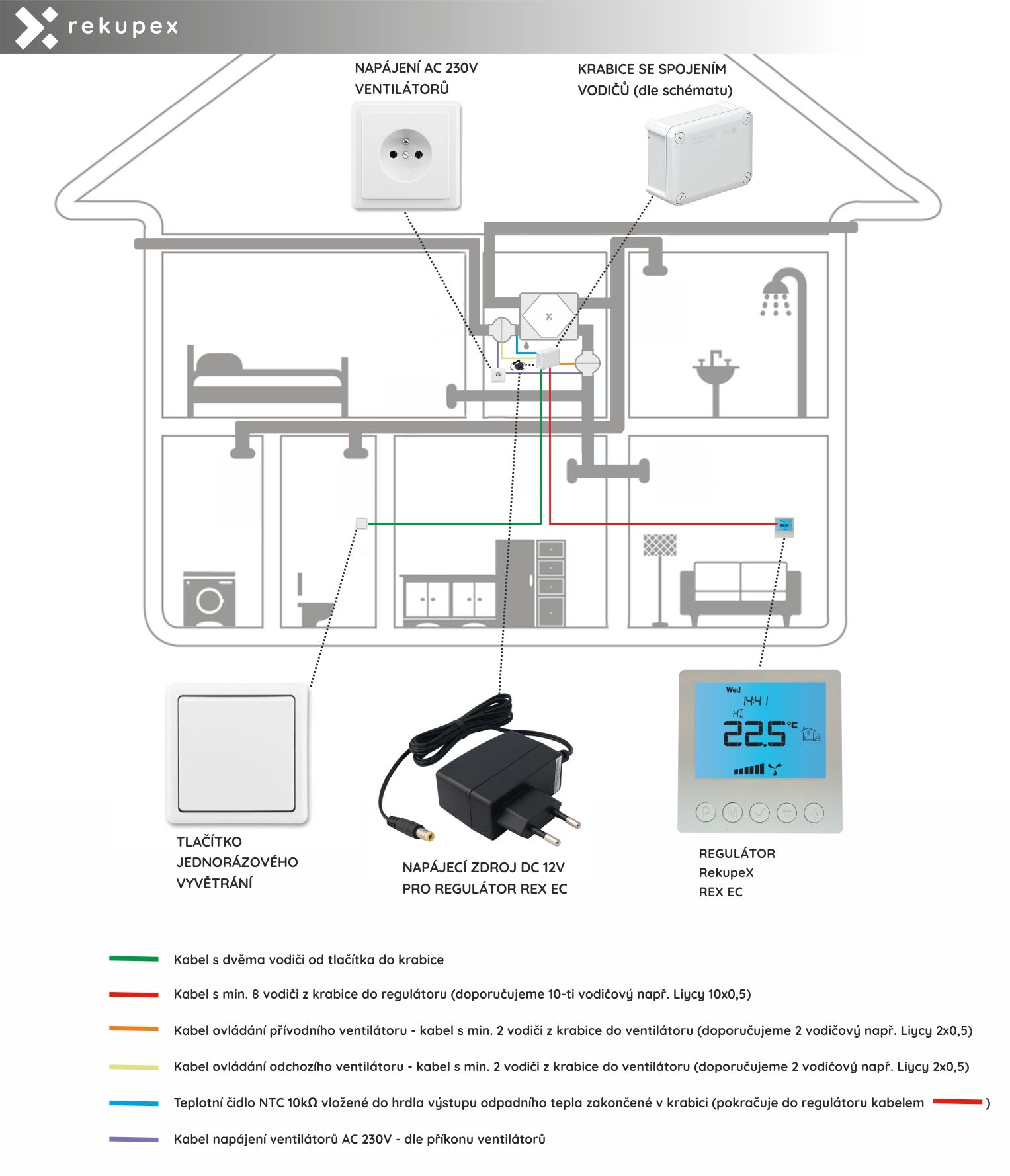
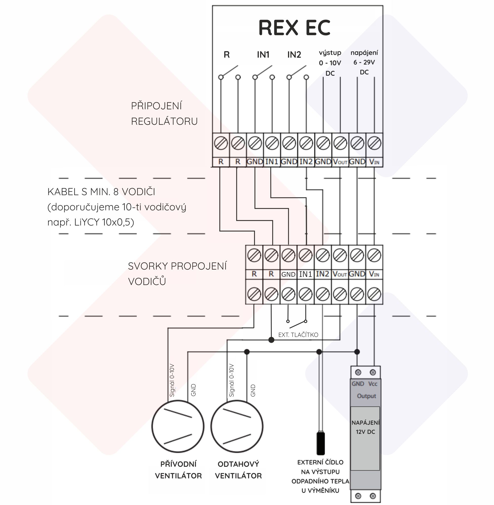
The RekupeX REX EC controller is an electronic controller with a large LCD display designed to control air handling units, recuboxes and recuperation sets with fans with EC motors. The controller allows you to control air handling units with a 0-10 V signal (e.g. with commutated motors) and with additional equipment. (switched contact) REX EC allows you to set the ventilation intensity based on a programmed work plan or works in manual mode.
Thanks to the switching contact (relay R), the controller has additional functions:
The controller, thanks to relay R, allows the device to be switched on (thermostat function - heating or cooling) based on the temperature measured by the built-in or external temperature sensor.
The controller can protect the heat exchanger of the heat recovery system against freezing . Based on the temperature measured by an external sensor located at the outlet of the polluted air from the exchanger, relay R enables the switching off of the fresh air supply fan in order to defrost the exchanger with polluted air or to switch on the preheating.
The controller also has a contact that, when short-circuited, starts the BOOST function - one-time ventilation. This allows you to control the heat recovery system from a remote location (WC, bathroom, kitchen, etc.) for the purpose of quick ventilation. There are 3 modes to choose from. And it can be started either by simply pressing a button or with a suitable additional sensor, e.g. humidity, etc.
FEATURES
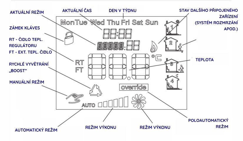
Large, backlit LCD display that displays the current fan speed, the temperature of the integrated and additional temperature sensor, the set mode, date and time, and other information.
TECHNICAL DATA
DELIVERY CONTENTS
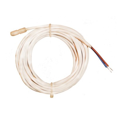
External temperature sensor not included (can be ordered separately)
EXPLANATION OF DISPLAY PICTOGRAMS
eight="335" />
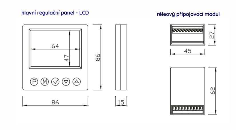
DIMENSIONS
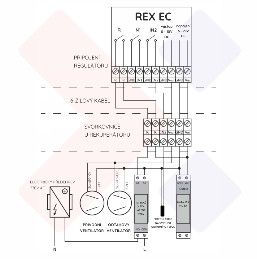
1./ PROTECTION AGAINST FREEZE OF THE HEAT EXHAUST UNIT - DISCONNECTING THE SUPPLY FAN
The controller in this connection is used to regulate a heat recovery system equipped with a supply and exhaust fan controlled by a 0-10V signal.
An external temperature sensor connected to IN2, physically located at the exhaust air outlet from the heat exchanger, indicates a temperature of e.g. 1°C and then the controller stops the supply fan. In this state, the warm air from the exhaust fan defrosts the heat exchanger with warm exhaust air.
2./ FREEZE PROTECTION OF THE HEAT EXHAUST UNIT - SWITCHING ON THE PREHEATING
The controller in this connection is used to regulate a heat recovery system equipped with a supply and exhaust fan controlled by a 0-10V signal.
An external temperature sensor connected to IN2, physically located at the exhaust air outlet from the heat exchanger, indicates a temperature of e.g. 1°C and then the controller starts the electric preheater located in the fresh air supply pipe in front of the heat exchanger.
Subsequently, the heated air defrosts the heat exchanger and the electric preheating is switched off (when the set temperature is reached - in this case at 3°C).
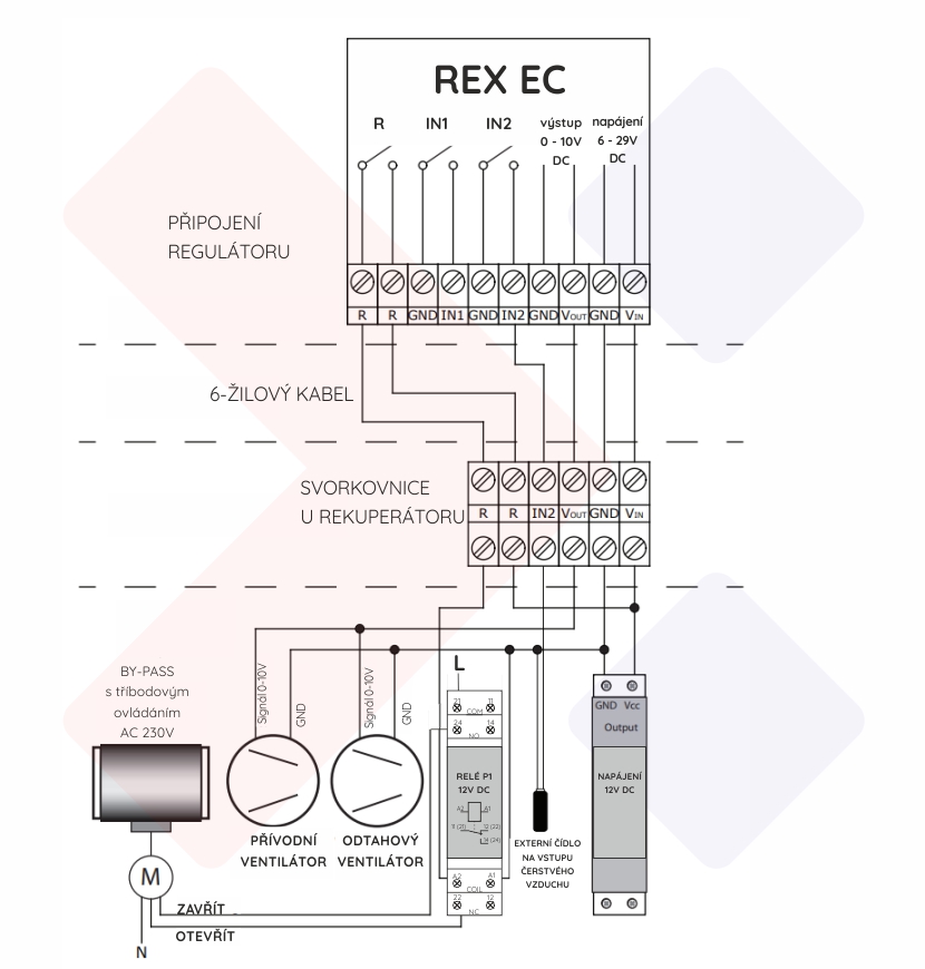
3./ AUTOMATIC BY-PASS CONTROL

Data sheet
regulation for a system with EC fans,
frost protection or BY-PASS control
programming of ventilation intensity,
monitoring filter replacement,
quick ventilation - control from the toilet,